I must admit, at first I didn’t think it could be possible to re-create a sound similar to old City Dial Tone with digital electronics. I read that the old dial tone frequencies were a combination of 120Hz and 600Hz, so I tried blending them in the same way I did for “Modern” dial tone. Here’s what that sounds like:Which sounds absolutely nothing like any City dial tone I ever heard. Yuck!
Equipment collector, Chuck Richards, explains exactly why that technique doesn’t work. Instead, he actually studied the oscilloscopic waveform of the famous GEdney-9 Panel dial tone and ingeniously created some clever electronic circuitry to replicate it:
A brief explanation about the difference between simply mixing two frequencies, (such as is done to make the 350/440 “precise” modern dialtone), versus using Amplitude Modulation (such as is done with the old 600 x 120 “city” dialtone).
When two waves are simply mixed together, the resulting waveform is additive only. Where two peaks happen at the same place, there will be one high peak. Where one wave goes positive from the zero line, and the other wave goes negative from the zero line, if they are the same magnitude at that point, they will add up to zero and the resulting wave will be at the zero line at that point.
With amplitude-modulation, things work differently. With that scheme, the fundamental wave (in this case 600 cycles) gets it’s amplitude (amplitude just means the height of the wave on the “y” axis) varied in accordance with the instantaneous value of the modulating wave. In the case of the 600 x 120 amplitude-modulated dialtone, the modulation happens at 120 cycles per second. The modulating wave controls the height of the modulated wave.
This is radically different than simple mixing. Mixing simply adds them. Amplitude Modulation, on the other hand has one wave’s height being constantly varied in accordance to the modulating wave. They are two distinctly different things. This is why any and all attempts to simply mix 600 Hz and 120 Hz, never even gets close to having an authentic sound. Same for any attempts at making the 420 x 40 ringback tone. It too is an AM signal.
By the way AM is the same as is used for AM radio. Only there, the high frequency radio carrier wave is amplitude modulated by the sounds to be sent out. The old rotary tone plants did the AM by using commutators and pole pieces. Today, we can make an electronic circuit which does very nearly the same thing that the old rotary machines did.
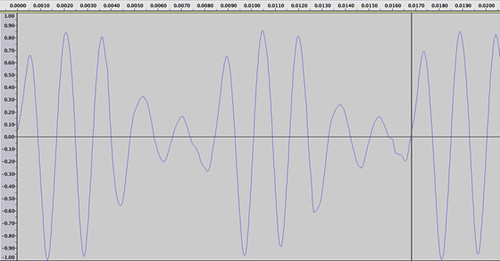
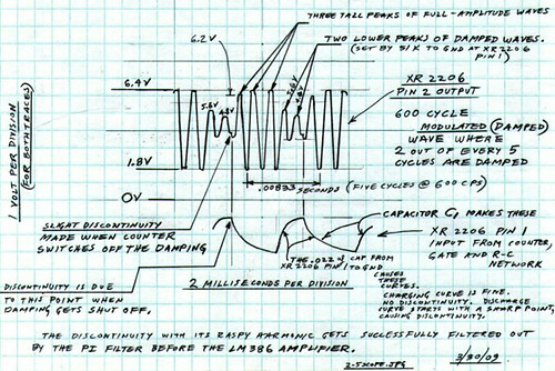
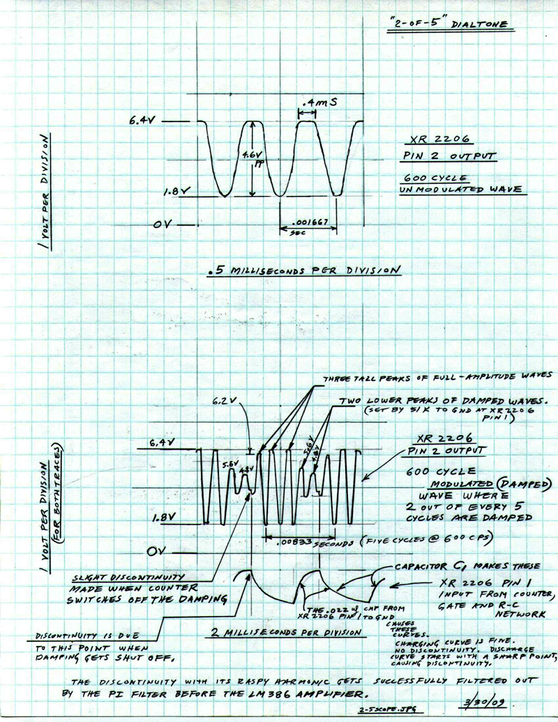
Looking closely at the GEdney-9 Dialtone waveform, we can see that one of it’s outstanding features is that it has three tall peaks, followed by two peaks that are of a lesser height. Those two peaks are apparently damped to a lesser value than the 3 tall peaks.
How do we do this electronically? One way is to count the waves using a counter. They get counted off in groups of 5 cycles each. Then, two out of every 5 cycles get singled out to be the ones that get damped down to a smaller amplitude. The signal to damp them gets fed to the XR-2206 at pin 1, which is the AM input.
This amounts to an odd form of amplitude modulation that’s a bit different than a pure AM signal. This particular method is really more of a “damped wave” form of modulation.
Once the counting of the 5 cycles has been done, and once any two consecutive cycles can be singled out for damping, then the remaining work to be accomplished in replicating accurately the old dialtone comes in finding the exact amount of damping to be applied each time to the two damped cycles, and then controlling the exact rate that they are damped and undamped.
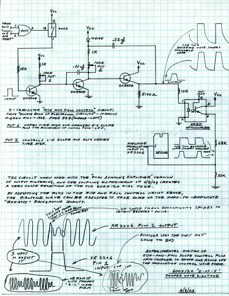
The parts associated with XR-2206 pin 1 are ones I used to get it close to the right amount of damping. Then, once the amount of damping is close, then the result starts sounding a lot more like the old dialtone. From there, further work can be done by filtering unwanted harmonics, and then amplifying the final result. The small discontinuity shown on the graph is the result of the abrupt dropoff at the end of the damping.
Later on, more experiments were done using a “rise-and-fall” control circuit that gets inserted after the output of the “or” gate which is operated by the 4017 counter. This rise and fall control adds a bit of slope to both the rising and falling edge of that signal. With that bit of slope to it, the control signal is not so abrupt, and therefore creates much less (or ideally no) discontinuity in the final output wave. With the use of the rise and fall control, together with much better filtering, a much nicer sounding rendition of the GEdney-9 dialtone is the result.
These are all experiments that anyone can do themselves. I have it all documented.
The fundamental idea though is that Amplitude Modulation is the key to making these old tones. In the end, it really does not matter what does the amplitude modulation. It can be done with 600 pounds of spinning iron and copper. Or it can be done using a few tiny bits of silicon. If it is done accurately, the results will sound accurate.
Hearing is Believing
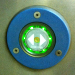
Here’s an actual call I made through Chuck Richards’ electromechanical step-by-exchange. You can hear his City dial tone and also a double-ringback tone. (I wasn’t expecting Chuck to answer!)
Now, here’s a side-by-side comparison of Chuck’s dial tone followed by GEdney-9 dial tone:
Here’s their waveforms. The top trace is Chuck Richards’ dialtone, with GEdney-9 on the bottom:
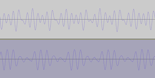
Chuck certainly did a great job of matching the pitch and some other sound qualities of GEdney-9, even though the waveforms appear different. Note that Chuck’s waveform is almost as smooth as “Modern” dial tone, and doesn’t have the little “snowflake” distortions that roughen up GEdney-9’s. Nonetheless, it’s a much better imitation that I ever thought would be possible!
- Chuck Richards’ 120 Line Western Electric Step by Step Switch

—from PanelSwitchman‘s collection on Flickr.
On the right side of this picture, mounted to the 23 inch rack, from the top down are: Main fuse panel. 48 volt DC power supply. Test Board. Relay plates.
- Chuck Richards’ Tone Plant

—from PanelSwitchman‘s collection on Flickr.
Full view of ITEC card cage. Two ITEC trunks at the left. Seven home made cards at the right.
Below are Chuck’s beautifully hand-drawn diagrams and his additional design notes:
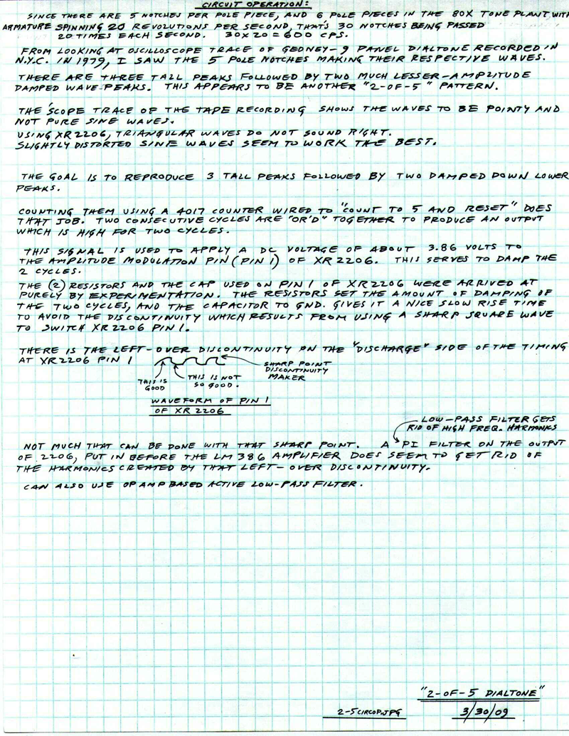
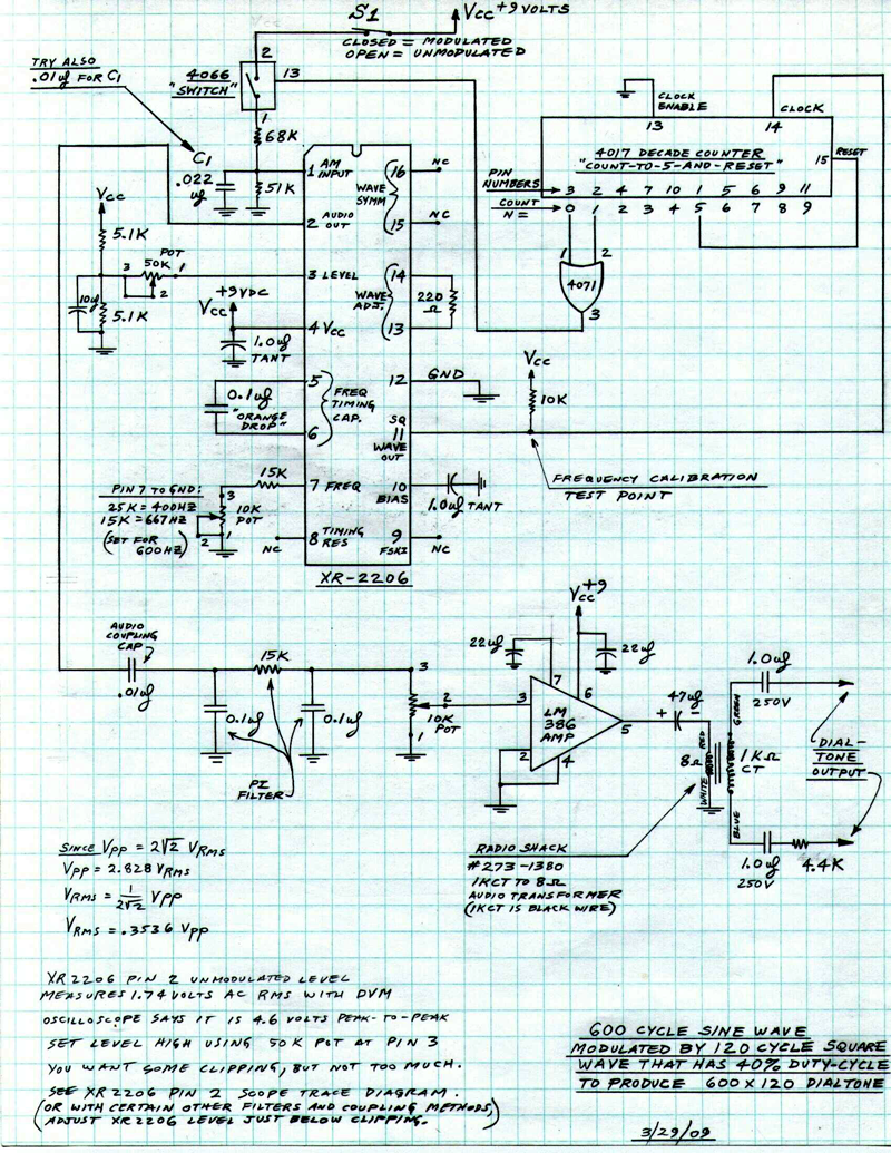
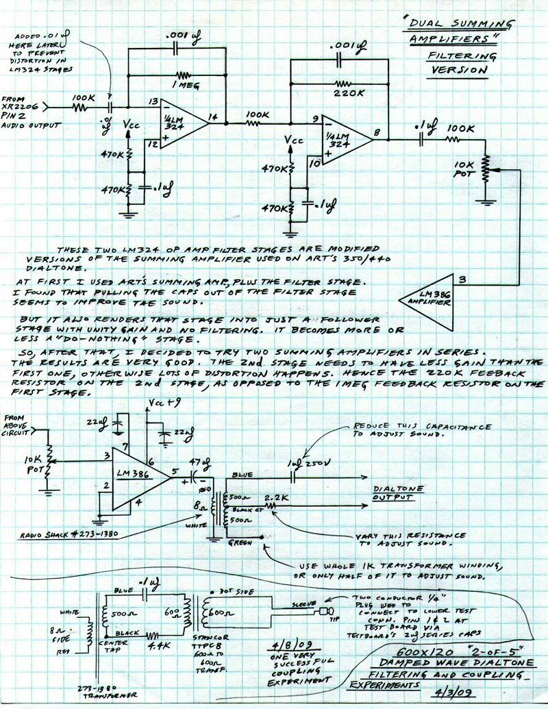
These are some refinements over the original simple circuit shown on page 1. (page numbers at lower right of each sheet). If it is built exactly as shown on pg. 1 it works quite well. Bill Guerts built it that way and he says it sounds fine. But, I did more experiments after that, and came up with pages 2 and 3.
To use the stuff on pages 2 and 3, you have to imaginarily break inand get rid of everything on page 1 from 4071, pin 3 to XR-2206 pin 1.Then subsitiute instead the circuit shown on page 2. This addition of the rise-and-fall control fixes up those discontinuities better. Also, on page 1 imaginarily disconnect and get rid of everything connected to XR-2206 pin 1, and replace it all with what is shown on page 3. This is much better filtering using two stages of LM324 op amps feeding the final LM386 audio amplifier. Final output shown in the two diagrams at bottom of pg. 3.
These schematics are sort of a mess right now, and to have a really clear picture of the actual final circuit, they need to be re-drawn without all the scratch notes. But for anyone who wants to start in and do the experiments, it’s all there. It all fits on a circuitboard about the size of a small postcard.
Chuck